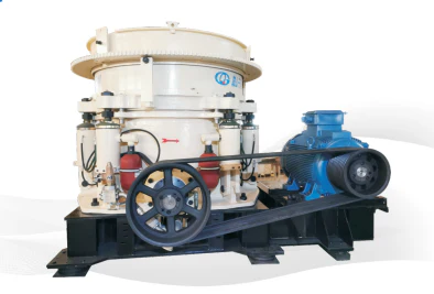
The HP500 Multi-Cylinder Hydraulic Cone Crusher serves as core equipment in mining and aggregate production lines, functioning as key unit for secondary crushing (intermediate crushing) or tertiary crushing (fine crushing). This crusher adopts a multi-cylinder hydraulic design, comprising 6 “iron-pass” release hydraulic cylinders and 8 locking hydraulic cylinders. Key structural components include: horizontal shaft, large/small bevel gears, main shaft, eccentric sleeve, spherical seat assembly, spherical bushing, moving cone assembly, fixed cone assembly, adjustment ring, and main frame. With its simple and compact structure, it enables automatic discharge opening adjustment.
Core Component Assembly Procedure
Step 1: Positioning of Lower Frame and Horizontal Shaft Assembly
Securely place the lower frame on the assembly platform and level it using shims.
Hoist the horizontal shaft assembly (including horizontal shaft, pinion, and bearings) into position and install it into the lower frame. Tighten the bearing housing bolts to the specified torque, ensuring the gear end face clearance meets drawing requirements.
Step 2: Installation of Eccentric Sleeve Assembly
This is the core of power transmission. Pre-assemble the eccentric sleeve, step washer (lower thrust bearing), and large gear in sequence.
Use a lifting tool to vertically hoist the entire eccentric sleeve assembly and carefully lower it into the lower frame, seating it on the step washer.
Critical point: Ensure proper meshing between the large gear and the pinion on the horizontal shaft. Rotate the horizontal shaft to check meshing clearance (typically measured with lead wire compression), ensuring it falls within the manual’s specified range.
Step 3: Precision Placement of Moving Cone Assembly
Pre-assemble the main shaft, moving cone body, and mantle into the moving cone assembly.
Apply lubricating oil to the spherical bushing at the lower end of the main shaft.
This is one of the most critical steps. Use a lifting tool to hoist the moving cone assembly perfectly vertically, slowly and steadily lowering it into the frame. The spherical bearing must seat on the spherical bushing while the main shaft smoothly enters the inner bore of the eccentric sleeve.
Any impact or scraping during placement is strictly prohibited.
Step 4: Assembly of Upper Frame and Fixed Cone Liner
Fixing the concave:
Carefully place the concave into the upper frame (adjustment ring).
Zinc alloy pouring is the standard and reliable method: Clean the bonding surfaces, seal gaps with molds, and pour molten zinc alloy through the filling holes until the space between the liner and frame is completely filled. Allow natural cooling and solidification to form a secure metal bond.
Note: The pouring process requires professional operation to prevent zinc splashing and ensure dense filling without voids.
Step 5: Integration of Upper Frame Assembly with Lower Frame
This demonstrates the “multi-cylinder hydraulic” concept:
Hoist the upper frame assembly with installed concave and slowly lower it to align with the lower frame.
Install the locking cylinders and multiple hydraulic cylinders (HP500 typically has several). Operate the hydraulic power unit according to the manual’s specified sequence and pressure to tension and lock the upper and lower frames together.
Critical point: Ensure all contact surfaces are clean and seals intact. Before final closure, reconfirm there’s no interference between the mantle and concave.
Step 6: Installation of Drive System and Guards
Install the pulley or coupling to the horizontal shaft end.
Mount the motor and perform precise alignment (for coupling drives) or parallelism adjustment (for belt drives). This is crucial for vibration reduction and extended equipment life.
Finally, install all protective covers and guards, ensuring they are secure and reliable – an essential requirement for safe operation.